Water level sensor placement guide title graphic with Waterline Controls logo and piping illustration
Written by Waterline Controls

Water Level Sensor Placement Guide

Water level sensor placement is the choice of where each sensing point sits in a tank, basin, sump or reservoir, and it decides when filling starts and stops, when alarms activate and whether pumps are protected from low water. A water level control system can only respond to the information it receives, so a sensor in the wrong place can make a good controller ineffective.

Proper positioning is a vital part of designing or upgrading an automatic water level control system. The sensing points should reflect the actual operating range of the equipment.

Start With the Normal Operating Water Level

Before deciding where sensors belong, determine the normal operating level for the application. A cooling tower basin, fire protection tank, wastewater sump and storage tank do not necessarily require the same control range.

In a fill application, the fill-start sensing point identifies when additional water is needed. The fill-stop sensing point determines when filling should stop. These points are separated to form an operating range, instead of switching the equipment on and off as the water surface moves.

The fill-start point must allow enough water for normal operation, and the stop point must leave enough space below the overflow level.

Keep Sensors Away From Misleading Water Movement

Water inside a tank is not always calm. Incoming water, pump suction, recirculation, turbulence and splashing can cause the level around one part of a vessel to behave differently from the overall water level.

Installing a sensor directly beside a forceful inlet can cause unnecessary switching because the sensor may repeatedly become wet and dry. Similar problems can occur where strong turbulence affects the sensing area.

The best location is one that represents the true level of the vessel as consistently as possible. This matters particularly where equipment cycles frequently or water is continuously moving.

Protect Pumps From Low Water Conditions

Sensor placement also plays a role in pump protection.

Once the level has fallen below a safe point, pumps that need a sufficient water supply should not be allowed to run. Operating a pump below its required water level can damage components such as bearings and shaft seals, so use the selected pump manufacturer’s minimum level and dry running limits.

A correctly positioned low level sensor can provide the signal needed to stop equipment, activate an alarm or initiate another programmed response before the water reaches a damaging level.

Its exact position depends on the system, including the pump intake, required reserve volume and the level at which continued operation becomes undesirable.

Leave Space for High Level and Overflow Protection

The upper sensing point should not simply be placed as high as physically possible. Tanks and basins need room between their normal full level and the point where water can escape.

The U.S. Department of Energy states that properly operated cooling towers should not have leaks or overflows, and recommends checking float control equipment and system valves to confirm the basin level is being maintained.

Where high level alarms are used, their sensing point should provide useful warning before an overflow occurs. The normal fill stop point and the high level alarm should perform separate jobs rather than respond at essentially the same height. On the WLC-5000 water level controller, for example, fill start, fill stop, high alarm and low alarm each have their own probe length. The difference between a high water alarm and an overflow alarm is covered in high water alarm vs overflow alarm for level controls.

Review Sensor Position When Conditions Change

A system that worked well when first installed may need review after equipment changes. A replacement pump, altered flow rate, new basin configuration, different operating level or changing water demand can affect the most useful sensing positions.

That makes sensor placement worth checking during upgrades and recurring maintenance. Operators should also look for physical changes around sensors that could interfere with consistent detection.

Controllers and Sensors for Defined Sensing Points

Reliable automatic control begins with accurate detection of the water level. Waterline Controls manufactures frequency-based level controllers and stainless steel sensors for cooling towers, tanks, sump systems, fire protection applications, HVAC equipment and other commercial uses. For help selecting a water level control system and setting sensing points for your application, call Waterline Controls at 480-905-1892.

References

U.S. Department of Energy: Best Management Practice #10, Cooling Tower Management

Waterline Controls water level control systems
WLC-5000 water level controller

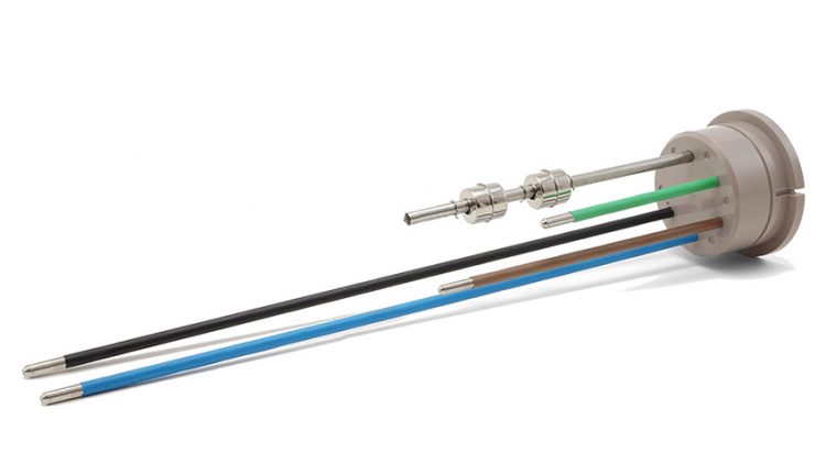
WLC Checkpoint OEM sensor for liquid level controls

High water alarm vs overflow alarm title graphic
Written by Waterline Controls

High Water Alarm vs Overflow Alarm

A high water alarm warns that the level has risen above its normal operating range. An overflow alarm is a project or code label for an alarm intended to warn of or prevent overflow, and specifications do not agree on where it sits. The actual sensor elevation and control sequence, not the label, decide whether either alarm gives useful response time.

An alarm that waits until water is already leaving the tank offers much less protection than one that warns while an operator or an automatic action can still respond.

Define the Normal Maximum First

Before locating the alarm, establish the normal fill stop level.

Automatic filling should stop at the intended operating level. The high alarm then sits above that point.

The WLC-5000 water level controller uses separate probes for fill stop and high alarm, allowing the controller to distinguish normal filling from an abnormal high water condition.

The distance between those points depends on the tank geometry and operating requirements.

High Level Means the Normal Sequence Has Been Exceeded

A high level alarm usually indicates that normal level control has not stopped the rise in water.

Possible causes include a leaking fill valve, a valve stuck open, incorrect control wiring or unexpected inflow.

The alarm therefore provides diagnostic information: the operator knows that the tank has moved beyond the normal control range. For that reason the high alarm should be a dedicated sensing point, independent of the points that run normal fill or pump control.

Overflow Is a Physical Condition

Overflow occurs when water reaches a path that allows it to leave the intended vessel.

That may be through an overflow pipe or over the edge of a basin.

Calling a sensor an overflow alarm does not necessarily tell the engineer whether it is located before, at or after that physical level.

The drawings should therefore show the actual sensor elevation instead of relying only on the alarm name.

Waterline Controls has previously discussed overflow alarms for cooling tower level control, including WLC models that combine high and low alarms with automatic level control. For tank applications, see the water tank level controller high water alarm guide.

Leave Enough Response Margin

The faster a tank can fill, the more important alarm margin becomes.

If the high alarm sits only a fraction below overflow during a high inflow condition, the facility may have little useful warning.

Consider the maximum inflow rate, available freeboard and whether the control system can automatically stop the incoming water.

An alarm intended only to summon an operator requires enough time for that person to respond.

Send the Alarm Somewhere Useful

A local light is valuable during maintenance, but it does little for an unattended mechanical room.

WLC controllers that include a high alarm, such as the WLC-5000, provide a dry contact that can send that condition to a BMS, BAS or other remote monitoring system. For the full point list, see which BMS points a water level controller should report.

The BMS alarm should identify the actual equipment and condition.

Avoid a generic message such as “Water Alarm” when “Cooling Tower 2 High Level” gives the operator much better information.

Test the Alarm Independently

During commissioning, confirm normal fill stops before the high alarm activates.

Then simulate the high level condition and verify the local indicator, remote contact and any connected audible alarm.

If the system is designed to close another valve or stop equipment at high level, verify that function as well.

Record the actual final elevation.

High Water Alarms and Level Controllers for Tanks and Towers

Waterline Controls manufactures frequency-based electronic water level systems with automatic filling, high and low water level controls and alarms and remote signaling for cooling towers, tanks, sumps and other commercial applications. Call 480-905-1892 to review your normal operating range, high water setpoint, freeboard and BMS requirements so the alarm provides useful warning before an overflow becomes a facility problem.

References

WLC-5000 water level controller with high and low alarms

Water level controls and alarms

Overflow alarms for cooling tower level control

Water tank level controller high water alarm

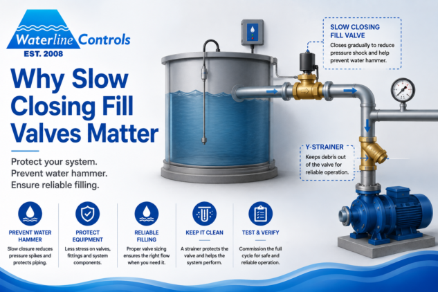
Slow closing fill valve and Y strainer on a tank fill line with a Waterline Controls level controller
Written by Waterline Controls

Why Slow Closing Fill Valves Matter

Water hammer is a pressure surge that occurs when moving water is stopped too quickly. The level controller may tell a fill valve exactly when to close, but the valve still has to stop the water in the pipe.

When a large flow is stopped very quickly, the resulting pressure change can create water hammer. Operators may hear a bang in the piping, but the concern goes beyond noise. Repeated pressure shock can place unnecessary stress on piping, fittings and valves.

For automatic tank and cooling tower fill systems, valve behavior deserves attention during design.

Fast Closure Can Create Pressure Shock

Water has momentum while it is moving through a pipe. A quick closing valve changes that velocity rapidly.

Watts, in its water hammer arrestor literature, explains that a sudden stop from a fast closing valve creates a shock that can damage pipes and appliances. The same surge occurs on large makeup lines.

Higher flow velocity and rapid valve closure increase surge risk, so pipe length, diameter, material, operating pressure and closure time should be evaluated together.

The required valve and surge control method depend on system pressure, pipe size, velocity and layout.

Slow Closing Solenoid Valves Reduce the Sudden Change

A slow closing valve does not simply delay the controller command. It changes how the valve physically reaches the closed position.

Emerson’s ASCO 221 series is specifically designed as a slow closing water solenoid valve. ASCO documentation states that its closing mechanism reduces the pressure spike associated with water hammer.

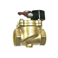
Waterline Controls offers slow closing valves for level control systems as accessories for its electronic level control systems.

The valve still needs to be sized for the actual application.

Match the Valve to the Water Supply

Do not select an automatic fill valve solely from the pipe diameter shown on a sketch.

Review required flow and Cv, minimum and maximum differential pressure, valve pressure rating, electrical supply and the time available to refill the basin or tank.

An oversized valve can raise velocity and overshoot the stop level while it closes, while an undersized valve can make recovery unnecessarily slow.

The project engineer should also confirm any requirements for backflow prevention and water supply protection.

Protect the Valve From Debris

Automatic valves work better when debris is kept out of the internal components.

Waterline Controls drawings commonly show a Y strainer upstream of the fill valve. The company also provides strainers and valve accessories for its systems.

A strainer still needs inspection and cleaning. A blocked strainer can reduce makeup flow and create a low level problem even when the controller and valve are operating correctly.

Watch for More Than Water Hammer

A fill problem can show up in several ways.

A valve that does not close completely may cause the level to creep upward after the controller has stopped calling for water. A valve that opens slowly or has inadequate flow may allow the basin to fall toward the low alarm during heavy demand.

The control system should therefore be commissioned as an assembly rather than testing the sensor and valve independently.

Verify the Complete Fill Cycle

Operate the system through a full cycle.

Confirm the controller calls for fill at the correct level, the valve opens fully, the water level recovers and the valve closes without excessive shock.

Then confirm that the high and low alarms remain outside the normal operating range.

If the BMS receives fill status, verify that point as well.

Fill Controllers, Slow Closing Valves and Strainers

Waterline Controls manufactures frequency-based electronic fill controllers for cooling towers, tanks, fire protection water tanks and other commercial applications, including the WLC-5000 fill controller with high and low alarms. The company also supplies valves, strainers and related accessories. If your project requires reliable automatic filling or you are dealing with repeated valve problems or piping shock, call 480-905-1892 to discuss the controller, valve type, operating levels and system requirements.

References

Slow closing valves for level control systems

Level control accessories

Watts: Water Hammer Arrestors

Emerson: ASCO Series 221 Slow Closing Water Solenoid Valve

What to Specify for Fire Water Tank Level Monitoring
Written by Waterline Controls

Fire Water Tank Level Monitoring Guide

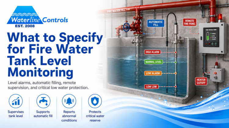
A fire water storage tank is not an ordinary process tank. Its level has to remain available for an emergency, while abnormal conditions must be reported clearly enough for facility staff to act. A gauge that only shows one condition at the tank may not provide the supervision, automatic filling and remote signaling expected for the project.

The final design depends on adopted codes, the fire protection plan and the authority having jurisdiction. A useful specification gives that team clear options instead of treating level control as a late plumbing accessory.

Confirm the Required Operating Level

Begin with the fire protection engineer’s required usable water volume and normal level. Controller setpoints should relate to that design, tank geometry and the elevations shown on the approved drawings.

NFPA guidance for fire protection water storage tanks addresses maintaining the required water level and supervising tank conditions. The local fire marshal may apply a particular adopted edition and local amendments, so the specification should not rely on a generic online diagram.

Define High, Low and Low Low Conditions

A low level alarm warns that available fire water has fallen below normal. A high level alarm can identify a fill valve problem or another condition that may cause overflow. Some projects also use a low low point for additional protection or heater cutoff.

Alarm descriptions should be specific. “Tank trouble” gives the operator little direction. Separate high, low, low low and power loss signals allow the remote system to display the actual condition.

Waterline Controls offers FPT fire protection tank level controllers with combinations of high alarm, low alarm, low low alarm, automatic fill and heater cutoff. The correct model depends on the approved sequence and which functions are handled elsewhere.

Decide Whether Filling Is Automatic

An automatic fill controller can open a valve when the level falls and close it after the normal level returns. That function should be coordinated with the water supply, valve type, backflow protection and municipal requirements.

Automatic filling does not replace supervision. A valve can fail, the supply can be interrupted or the tank can lose water faster than it is replaced. The remote system still needs to report abnormal conditions.

Plan Remote Fire Panel Connections

The level controller should connect to the approved remote fire panel or supervisory system using the required contact arrangement. Waterline Controls states that its FPT series integrates with existing remote fire panels. Potter also offers a float operated supervisory switch specifically for sprinkler supply tanks, showing that tank level is treated as a dedicated supervisory function.

Create a point list showing each signal, normal contact state and destination. Include controller power loss when required. The fire alarm contractor, electrical contractor and level control supplier should review the interface before installation.

Protect Against Power Loss and Cold Conditions

A level system that loses power should not appear normal. Decide how the panel will indicate loss of controller power and whether the remote signal is fail safe.

In cold climates, a tank heater or related equipment may need protection when water falls to a critical level. Waterline Controls offers the FPT-61T level controller with heater cutoff alongside high and low alarms. Heater operation and low water protection should follow the project design and equipment instructions.

Choose Sensor Locations Carefully

Sensor elevations should be measured from a fixed tank reference and documented on the approved drawing. Avoid placing the sensing assembly where incoming water creates misleading turbulence or where internal piping or maintenance work can damage it.

The sensor material and mounting assembly should suit the tank and water. Future access also matters. A technician must be able to inspect and test the system without removing unrelated equipment.

Commission Every Function

Testing should simulate each level condition and confirm local indication, fill valve response, remote panel signal and alarm restoration. Test power loss and any heater cutoff or low water interlock.

Record the final sensor elevations, relay states and sequence of operation. Facility staff should know how to use the test feature and how often the system must be inspected under the applicable fire protection program.

Specify Fire Tank Controls With Waterline Controls

Waterline Controls manufactures electronic FPT level control systems for fire water tanks, including alarm only models and configurations with automatic fill, high and low alarms, low low indication and heater cutoff. The systems are assembled in the United States and designed for remote panel integration. Call 480 905 1892 to discuss the approved sequence, tank dimensions, sensor arrangement and municipal requirements for your project.

References

Fire protection water tank level controls (FPT series)

FPT-61T fire tank level controller with heater cutoff

How To Reduce Water Waste?
Written by Waterline Controls

How To Reduce Water Waste?

Most people do not waste water on purpose. It usually happens in quieter ways, a toilet that keeps running, an irrigation system that waters when it should not, a faucet that drips just enough to ignore, or a building system that no one is watching closely. That is why reducing water waste is rarely about one dramatic change. It is more often about noticing the little losses and fixing them before they become expensive habits.

The good news is that real water savings usually come from practical steps, not complicated ones. Once you know where water is being lost, it gets much easier to do something about it.

START WITH LEAKS

If there is one place to begin, it is leaks. A small leak can seem harmless for weeks or months, especially if it is hidden behind a wall, under a sink, or somewhere outside that no one checks very often. But over time, those small losses add up.

That is why regular monitoring matters. Instead of waiting for a high bill or visible damage, it makes far more sense to catch unusual water use early. In homes, that may mean checking toilets, faucets, hose bibs, and irrigation lines. In commercial buildings, it often means paying closer attention to system data, usage patterns, and after-hours flow. When water is being used at the wrong time, that is usually telling you something.

PAY ATTENTION TO IRRIGATION

Outdoor watering wastes an enormous amount of water when it is not managed well. Sprinklers run during the heat of the day, water blows onto pavement instead of landscaping, or a timer keeps watering after a rainstorm because no one updated the schedule.

A better approach is to water only when needed and to make sure the system is actually helping the landscape instead of the sidewalk. Smarter controllers, weather-based scheduling, and routine inspections can make a real difference. Even simple adjustments, like changing watering times or fixing a misaligned sprinkler head, can cut waste more than people expect.

UPGRADE OLD FIXTURES AND CONTROLS

Sometimes water waste is built into the equipment itself. Older toilets, faucets, showerheads, and irrigation controls often use more water than necessary simply because they were designed to older standards. Replacing outdated fixtures with more efficient options can reduce waste without making everyday use feel inconvenient.

The same idea applies in larger buildings. If a property is still relying on older monitoring methods or no monitoring at all, waste can go unnoticed for far too long. Better controls give owners and managers a clearer picture of what the building is actually doing.

USE DATA, NOT GUESSWORK

One of the biggest reasons water waste continues is that people assume they would know if something was wrong. Often, they would not. Many leaks are hidden, and many forms of waste happen gradually enough that they look normal until the bill arrives.

That is where monitoring becomes valuable. Real-time water tracking, alerts, and usage reporting help turn water management from guesswork into something measurable. Instead of reacting after the damage is done, you can respond when the pattern first changes. For businesses, schools, hospitals, and large facilities, that shift can save both water and money.

MAKE WATER EFFICIENCY PART OF ROUTINE MAINTENANCE

Water waste is easier to control when it becomes part of normal maintenance rather than a once-a-year concern. Checking for leaks, reviewing usage trends, inspecting irrigation, and replacing worn components should be part of the regular rhythm of running a property.

That does not just protect water. It protects budgets, buildings, and equipment too. Waste is rarely just a water problem. It is usually a sign that something else needs attention.

READY TO GET SERIOUS ABOUT WATER WASTE?

If you want to reduce water waste without relying on guesswork, Waterline Controls offers solutions that help monitor water use, detect leaks, and improve visibility across building systems. The right setup can help you catch problems earlier, use water more efficiently, and make smarter decisions about your property. Reach out to Waterline Controls to learn more about practical water monitoring and leak detection options.

REFERENCES

Waterline Controls
Water Management in Intelligent Buildings and IoT, Waterline Controls
Fire Protection Archives, Waterline Controls
WaterSense, U.S. EPA
Start Saving, U.S. EPA WaterSense
About WaterSense, U.S. EPA
Using Water Efficiently, U.S. EPA WaterSense

Our level sensors and controls aren’t just for use in residential potable water holding tanks; some of the other applications include cooling towers, sump pumps, wastewater, boilers, water storage tanks, and building fire protection water tanks.

Water Level Controller Guide
Written by Waterline Controls

Water Level Controller Guide

You know how easy it is to forget about a water tank until something goes wrong if you’ve ever had to keep an eye on one. The tank might run low at times, which means the pump runs out of water. At other times, it fills up too much and the water goes to waste. A water level controller is meant to remove that stress off your hands by maintaining the water at the proper level on its own.

The idea behind these systems is simple, yet they may make a major impact in how well a water system works.

What Is a Water Level Controller?

A water level controller keeps an eye on how much water is in a tank and operates a pump depending on that level. The controller automatically turns the pump on and off, so someone doesn’t have to handle it by hand.

The pump turns on when the water level goes below a certain threshold. The controller turns off the pump when the tank is full and reaches the top. It’s a simple operation, but it prevents a lot of the difficulties that come up when people handle tanks by hand.

How Controllers for Water Levels Work


Most controllers use sensors that are put in different places inside the tank. The system knows whether the water level is too low or too high because of these sensors.

Some systems use float switches that move up and down with the water. Some people utilize electrical probes or sensors to find out how deep the water is. The approach may change, but the aim is always the same: to maintain the water level consistent without having to watch it all the time.

Once the controller is set up and installed, it works silently in the background and doesn’t need any maintenance.

Why It’s Important to Control the Water Level


It’s easy to forget how much stress bad water level control may create on a system. Pumps that run too much or run out of water wear down more quickly. Tanks that are over full might waste water and even harm the region surrounding the tank.

A water level controller can help keep these things from happening. It preserves equipment, saves water, and cuts down on the need for regular monitoring by keeping the system functioning within the correct parameters.

The best thing for many homeowners and facility managers is just peace of mind.

Where to Use Water Level Controllers


More sites than most people know employ water level controls. People who live in homes with storage tanks depend on them to keep the water flowing. They help farms and irrigation systems use water more effectively. They are typically used to keep cooling systems and process tanks running smoothly in commercial buildings and factories.

It is crucial to keep the proper level of water in any place where it is kept or pumped, and automation makes that much easier.

How to Pick the Right Water Level Controller


Not all systems are the same, so the size of the tank, the type of pump, and the place where everything is set up will determine which controller is best. Some installations demand highly fine control, while others merely need a simple, dependable system.

Talking to someone who works with these systems on a daily basis might help you avoid making mistakes and pick equipment that will last.

Our level sensors and controls aren’t just for use in residential potable water holding tanks; some of the other applications include cooling towers, sump pumps, wastewater, boilers, water storage tanks, and building fire protection water tanks.

Water Level Controller Guide
Written by Waterline Controls

How To Install A Water Level Indicator

Installing a water level indicator can be a straightforward DIY project or a more technical job, depending on the type of system (mechanical, float-based, sensor-based, or electronic). Below is a general step-by-step guide for installing a basic electronic water level indicator system for a standard overhead tank.

🧰 What You’ll Need:

  • Water level indicator kit (includes sensors, control unit, wires, and possibly a display)

  • Power drill

  • Waterproof silicone or sealant

  • Electrical tape

  • Screwdriver

  • Cable clips or zip ties

  • Ladder (if the tank is elevated)

🪜 Step-by-Step Installation Guide

✅ 1. Turn Off Power

Always start by turning off the main power supply if you’re working with electrical devices.

✅ 2. Mount the Control Unit

  • Choose a dry, accessible location near the tank or inside your house (depending on the model).

  • Mount the control/display unit on a wall using screws.

✅ 3. Install Sensor Probes in the Tank

You typically need 3 to 5 probes (depending on your system), which measure:

  • Empty/Low level

  • Middle level

  • Full/High level

  • (Optional) Overflow or critical low

How to install:

  • Drill small holes on the tank lid or side wall near the top.

  • Insert the probes or float sensors to the corresponding depths (use the manual to know the exact position).

  • Seal around the holes using waterproof silicone to prevent leakage.

  • Secure the sensor wires with cable clips inside or along the tank body.

✅ 4. Connect Wires to the Control Unit

  • Use the labeled diagram in your kit’s manual to match each sensor wire to its terminal.

  • Typically, wires run from each sensor to a central controller unit via color-coded terminals (e.g., red = full, yellow = mid, green = low).

  • Use electrical tape to secure connections and prevent short-circuits.

✅ 5. Test the System

  • Turn the power back on.

  • Slowly fill the tank and monitor the display or indicator lights.

  • The control unit should light up or beep as water reaches each sensor level.

✅ 6. Optional: Connect to Pump

If your indicator supports pump automation:

  • Connect the pump’s power relay to the controller as instructed.

  • The system will automatically turn the pump on when water is low and off when full.

🔒 Safety Tips:

  • Always use waterproof-rated wires and connectors.

  • Keep control units protected from rain and moisture.

  • Don’t overtighten sensors; water tanks expand slightly when filled.

🛠️ Types of Systems You Can Install:

Type Difficulty Features
Float-based Easy No electricity needed; mechanical
Electrode/probe Moderate Common in homes; needs wiring
Ultrasonic sensor Moderate No contact with water; more accurate
Smart IoT systems Hard Remote monitoring via smartphone

Our level sensors and controls aren’t just for use in residential potable water holding tanks; some of the other applications include cooling towers, sump pumps, wastewater, boilers, water storage tanks, and building fire protection water tanks.

How Waste Water Treatment Works
Written by Waterline Controls

Water Tank Sensor Prices: A Comprehensive Guide

The price of water tank sensors can vary significantly based on the type, features, accuracy, and brand. Here’s a comprehensive guide to water tank sensor pricing to help you choose the right option for your needs and budget:


Types of Water Tank Sensors and Their Price Range

  1. Float Sensors:
    • How They Work: Use a floating device that rises or falls with the water level to trigger a switch or signal.
    • Price Range: $10–$50 (basic models), $50–$100 (advanced models with multiple floats for precise readings).
    • Applications: Residential tanks, irrigation systems.
  2. Ultrasonic Sensors:
    • How They Work: Emit ultrasonic waves to measure the distance between the sensor and the water surface.
    • Price Range: $50–$300.
    • Applications: Industrial water tanks, commercial setups requiring non-contact measurement.
    • Features: Accurate, non-invasive, and suitable for harsh environments.
  3. Conductivity/Capacitive Sensors:
    • How They Work: Detect water level based on the conductive or capacitive properties of the liquid.
    • Price Range: $20–$150.
    • Applications: Water purification systems, small tanks, and electronic circuits.
  4. Pressure Sensors:
    • How They Work: Measure water pressure at the bottom of the tank to calculate the water level.
    • Price Range: $30–$200.
    • Applications: Deep water tanks, underground reservoirs.
  5. Radar Sensors:
    • How They Work: Use radar waves to measure water level without physical contact.
    • Price Range: $200–$1,000 or more.
    • Applications: Industrial and high-precision setups.
    • Features: High accuracy, works in extreme temperatures, suitable for large tanks.
  6. Smart Sensors:
    • How They Work: Combine sensor technology with IoT features for remote monitoring via apps or cloud platforms.
    • Price Range: $100–$500.
    • Applications: Smart homes, advanced industrial systems.
    • Features: Wireless connectivity (Wi-Fi, Bluetooth), real-time data, and alerts.

Factors Influencing Water Tank Sensor Prices

  1. Type of Technology:
    • Basic mechanical sensors are cheaper than advanced ultrasonic or radar sensors.
  2. Accuracy and Range:
    • Sensors with higher precision and longer range tend to cost more.
  3. Build Quality and Materials:
    • Sensors made with corrosion-resistant materials (e.g., stainless steel) are pricier but more durable.
  4. Brand Reputation:
    • Established brands often charge a premium for reliability and customer support.
  5. Additional Features:
    • Features like remote monitoring, multiple output options, or compatibility with existing systems can increase costs.
  6. Size and Application:
    • Industrial-grade sensors are usually more expensive due to their robust design and advanced features.

Popular Brands and Their Approximate Pricing

  1. Honeywell: $100–$400 (advanced pressure and ultrasonic sensors).
  2. Siemens: $200–$1,000 (industrial radar and ultrasonic sensors).
  3. Xiaomi or Smart Home Brands: $50–$200 (IoT-enabled sensors for home use).
  4. TankMate: $50–$150 (affordable float and smart water level sensors).
  5. Omron: $30–$300 (versatile pressure and float sensors).

Where to Buy Water Tank Sensors

  1. Online Retailers:
    • Amazon, eBay, and Alibaba often offer competitive pricing and variety.
  2. Specialized Stores:
    • Plumbing and industrial supply shops for professional-grade sensors.
  3. Direct from Manufacturers:
    • For bulk purchases or custom specifications.

Budget Recommendations

  • For Residential Use: $20–$100 (float or basic ultrasonic sensors).
  • For Smart Homes: $100–$300 (IoT-enabled smart sensors).
  • For Industrial Applications: $300–$1,000+ (radar, high-precision ultrasonic, or pressure sensors).

Additional Costs to Consider

  • Installation: $50–$200, depending on complexity.
  • Maintenance: Periodic cleaning and calibration costs, especially for advanced models.
  • Accessories: Mounting brackets, power supplies, and connection cables.

By understanding the types, features, and price ranges of water tank sensors, you can select one that meets your specific needs and budget while ensuring long-term reliability and functionality.

Water Level Controller Guide
Written by Waterline Controls

History of Water Level Sensors

Water level sensors have a long history dating back to ancient times when simple devices were used to measure water levels for irrigation and flood control. Over the centuries, advancements in technology have led to the development of more sophisticated water level sensing devices for various applications. Here’s a brief overview of the history of water level sensors:

  1. Ancient Water Level Measurement: The earliest water level measurement devices were simple float-based mechanisms used by ancient civilizations for irrigation and flood control. These devices typically consisted of a float attached to a lever or rod, which would rise and fall with the water level, indicating the depth.
  2. Early Mechanical Water Level Gauges: In the 17th and 18th centuries, mechanical water level gauges were developed for use in wells, reservoirs, and other water storage systems. These gauges often used a float connected to a chain or pulley system to measure the water level.
  3. Development of Electrical Sensors: The invention of electrical conductivity and capacitance sensors in the 19th century paved the way for more accurate and reliable water level measurement devices. These sensors could detect changes in water level by measuring changes in electrical properties such as conductivity or capacitance.
  4. Ultrasonic and Radar Sensors: In the mid-20th century, ultrasonic and radar-based water level sensors were developed, offering non-contact measurement capabilities. These sensors emit sound or radio waves that bounce off the water surface and are then detected to determine the water level.
  5. Pressure Transducers: Pressure transducers, which measure water level based on the pressure exerted by the water column, were also developed in the 20th century. These sensors are commonly used in applications such as groundwater monitoring, sewage systems, and industrial tanks.
  6. Modern Sensor Technologies: In recent decades, advancements in microelectronics and sensor technologies have led to the development of highly accurate and versatile water level sensors. These sensors often use a combination of different measurement principles, such as ultrasonic, pressure, capacitance, or optical sensing, to provide precise and reliable water level measurements in various environments.
  7. Wireless and IoT Integration: With the rise of wireless communication and Internet of Things (IoT) technologies, water level sensors can now be easily integrated into remote monitoring and control systems. These systems allow for real-time monitoring of water levels and automated alerts or actions based on predefined thresholds.

Today, water level sensors are widely used in various applications, including environmental monitoring, flood warning systems, water resource management, wastewater treatment, agriculture, aquaculture, and industrial process control. Continued advancements in sensor technology are expected to further enhance the accuracy, reliability, and functionality of water level sensing devices in the future.

Our level sensors and controls aren’t just for use in residential potable water holding tanks; some of the other applications include cooling towers, sump pumps, wastewater, boilers, water storage tanks, and building fire protection water tanks.

Types of Sump Pumps and Switches
Written by Waterline Controls

Types of Sump Pumps and Switches

Sump pumps and their trusty companions, the switches, work together to keep your basement or crawl space safe from watery woes. Read on to learn more!

Sump Pump Types:

  • Submersible Pumps: These workhorses live and breathe underwater! They sit in the sump pit directly, using an electric motor to power an impeller that forces water out through a discharge pipe. Submersibles are efficient, quiet, and ideal for most residential applications.
  • Pedestal Pumps: These prefer dry land! The motor sits atop a pedestal outside the sump pit, connected to the pump impeller by a long shaft. Pedestal pumps are less prone to clogging but can be louder and take up more space.

Sump Pump Switch Types:

  • Tethered Float Switches: The classic! A buoyant float attached to the pump by a tether rises with the water level, eventually pulling a lever or activating a micro-switch to turn on the pump. Simple and reliable, but prone to snags and require space for the tether’s movement.
  • Vertical Float Switches: These sleek operators use a rod and float mechanism directly within the sump pit. As the water rises, the rod pushes against a lever to activate the switch. More accurate and discreet than tethered floats, but may require specific sump pit dimensions.
  • Diaphragm Switches: These pressure-sensitive marvels utilize a diaphragm that flexes with rising water, pushing against a switch internally. No moving parts in the water, making them clog-resistant and suitable for dirty or sandy water.
  • Electronic Switches: High-tech heroes for the sump pump world! These rely on sensors like pressure sensors or ultrasonic sensors to detect water level changes and activate the pump. Offer precise control and advanced features, but can be pricier and require proper installation.

Choosing the Right Combination:

The ideal duo for your sump pump system depends on your needs and preferences. Consider factors like:

  • Sump pit dimensions and configuration.
  • Water level fluctuation and expected debris levels.
  • Desired noise level and budget.
  • Need for advanced features like automatic backup or alarm systems.

Consulting a qualified plumber or sump pump specialist can help you choose the perfect sump pump and switch combination for your specific situation, ensuring a dry and worry-free basement for years to come

Why Choose Water Line Controls

All of our water level controls and water level control systems are assembled right here in the U.S.A. where we monitor every step of the process.

1 2