Why Reliable Water Level Control Matters In Commercial Sump Systems
A commercial sump system is easy to ignore when it is working. It sits there quietly, doing a job nobody wants to think about too much.
Then one day it does not work.
Maybe the pump does not turn on. Maybe it runs too often. Maybe the basin level gets higher than it should. Maybe there is an alarm after hours and nobody is quite sure what happened. In a commercial building, that kind of problem can move from annoying to expensive very quickly.
That is why water level control matters so much. The pump is important, of course, but the pump can only respond to the signal it receives.
Float Switches Can Be The Weak Link
Many sump systems still rely on mechanical float switches. They are familiar, simple, and easy to understand. The problem is that commercial sump environments are not always gentle places for moving parts.
A float can hang up. It can get caught on debris. It can shift out of position. It can fail after years of use. In some basins, grease, sediment, scale, or general buildup can make the problem worse.
It may also cycle too often or shut off at the wrong time. Either way, the issue is not just the float. It is the risk that comes with unreliable level control.
Bad Level Control Can Wear Out Equipment
A sump pump that short cycles is not just annoying. It can put extra wear on the components.
If the water level is not being read correctly, the system may run more than needed or fail to run soon enough. That can shorten equipment life and make maintenance harder to predict.
For facility managers, maintenance teams, and building owners, predictable operation matters. Nobody wants to keep solving the same sump issue every few months because the control setup is not dependable.
Alarms Give People Time To Act
One of the most useful features in a commercial sump setup is a good alarm system.
A high level alarm can warn the team before a serious overflow. A low level or fault signal can also help identify unusual behavior. In larger buildings, the ability to connect with a building management system can make a big difference because the right people can see the problem sooner.
That extra warning time matters. It can be the difference between a manageable service call and a cleanup nobody wanted.
Electronic Controls Remove A Common Failure Point
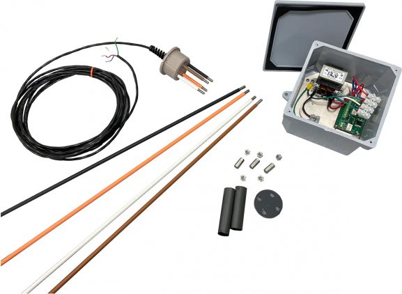
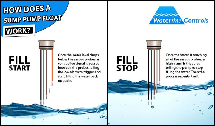
Electronic water level controls can help by removing the traditional mechanical float from the system. Instead of depending on a float moving up and down, the system uses sensors and a controller to manage pump operation and level detection.
That can be useful in sump basins where conditions are rough, access is awkward, or downtime would be a real problem.
No system should be forgotten forever, but a better control setup can reduce some of the nuisance failures that come from old float switches and hard working mechanical parts.
When To Look At An Upgrade
It may be time to review your sump level controls if the pump cycles too often, the basin level is inconsistent, alarms are unreliable, or float switches have to be replaced more than they should.
It is also worth looking at the controls during a pump replacement, building upgrade, or maintenance review. If the pump is being serviced anyway, that is a sensible time to ask whether the controls are helping or creating more work.
Talk To Waterline Controls
Waterline Controls manufactures electronic water level controls and sensors for sump systems, cooling towers, tanks, fire protection, HVAC systems, and other wet environment applications.
If your commercial sump system has been relying on float switches and giving your team repeated problems, Waterline Controls can help you look at a more reliable way to manage water levels.
Contact Waterline Controls today to learn more about electronic water level controls for commercial sump systems