Identifying Water in Transit in Cooling Towers
While our system is simple to use and install, some theories and terms can be good to review before proceeding. With this in mind, let’s talk about the ‘hidden’ water in a typical cooling tower system. The terms we will be talking about here are “Freeboard” and “Water in Transit”.
Freeboard – This is a civil engineering term used to describe the distance between the normal operating level of an environment and the space allowable to fill without overflowing any reservoir. For our purposes we will use this term to describe the distance between the minimum operating level (that is an acceptable level to allow all the other features and functions of the system to operate properly, such as pumps and valves and piping) and the overflow level (the point at which it dumps to waste and cannot be recovered).
Water In Transit – Describes the water moving through the system while it is operating, that has the potential to get back to the basin/holding tank and filling the freeboard.
Needed Calculations
How to calculate and evaluate freeboard and water in transit
The needed space can be calculated by measuring the water in transit in gallons and then figuring how much space is needed inside the basin/tank.
- Calculate the volume in the pipes by using the volume of a cylinder formula where the measurements are in feet.
- Multiple that cubic dimensions by 7.5 (since there are 7.48 gallons of water in a cubic foot).
- Calculate how much water is in every inch of the tank by using Length x Width x 0.0833 x 7.5 or using the volume formula where the height of 1” = 0.0833Ft.
The rule of thumb for cooling tower water in the system is one half of the GPM of the tower.
Verification
This is a good estimate and now it should be validated by setting a level in the tank as a minimum operating level and see if there is going to be enough freeboard to capture the water in transit. We all tend to want an extra 2 or 3 inches for whatever reason so add the space if you have it. This freeboard will be required to capture this water every time the system turns off. When or if the demand changes because someone adds more piping (equals more water in transit) or more water capacity in any form then the required freeboard changes in the same manner.
Dangers of Older Level Control Systems
Just because the system is adding water it does not mean that the volume of water is increasing. The water that is being added is caused by the need to dump water or water evaporating, so water in is equal to water out. Typically, setting a water level in these types of environments should not be set up on a long term basis with a mechanical float switch of any sort, you should use a system like WaterLine Controls™. The reason is because float switches are mechanical and set to operate at the minimum operating level but whenever the system is turned off the float switch is stressed in the opposite direction. This occurrence over time affects the set point but also has the potential for mechanics of some float switches to fail, allowing water to run freely into the tank and out the overflow.
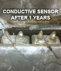
With our WLC System there are no floats in the water, it is a sensor driven system where the water is free to move up and down the probes and this up and down movement has no effect on the probes since they do not move. Also, with a WLC system, there is the ability to send the sensor activation points to an automation system or BACso the set points in the tank can been “seen” electronically and acted upon, if necessary – That cannot be accomplished with a mechanical float.
Some Real World Examples
Recently, we have been running into cases where the operator is replacing an old water level controller that either had water volume control issues in the past or the demand on the system has changed because someone has added volume requirement capacity. When they go to put a WLC unit in, or for that matter any level controller back in, every time the system turns off the cooling tower basin/holding tank overflows into the drains and the excess water then goes to waste.
We have been told many stories about these catastrophic float switch failures where companies lose tens of thousands of gallons of water and thousands of dollars. This next example is where the demand had changed and the level was dropped to accommodate the change. In this case the water was set in the original design to be an air barrier so as to force all the air through the fill material. When they lowered the level that barrier disappeared and air would now take the least path of resistance under the fill between the fill and the water level. More airflow along the bottom caused the fill to dry out since there was now more airflow across this area from lower resistance. This now caused all of those other issues related to dried out fill and poor air movement through the fill reducing efficiency. The only way to make this operate as designed is to add an external tank to capture the added water in transit.
PROUDLY MADE IN THE U.S.A. 
All of our liquid level controls and liquid level sensors are assembled right here in the U.S.A.
where we monitor every step of the process.
NOT SURE WHAT YOU NEED? JUST CALL BECAUSE WE’RE HERE TO HELP! 480-905-1892
We offer products comparable to the products offered by the above companies. See our website pages for further information on the products. The tradenames and trademarks in this page are owned by their respective companies or are the same name as the company. They are mentioned for comparison purposes only. They are in no way affiliated with System Dynamics, Inc or WaterLine Controls.
